


MIDI Out module for Yamaha
FX/FS series Electone organs
Back in college, one of the classes I took, Music and History of the Baroque, made a lasting impression on me. One day the professor took us across the street to a church that had a tracker pipe organ. The organist played some Bach and Buxtehude, and then invited us up into the loft to learn about the organ, and even let us each play a few notes. Since then, I’ve had an interest in playing, but the only organ I have access to is the electronic organ at my church, a Yamaha Electone FX-20. The voices are okay, but lack the character of a real pipe organ.
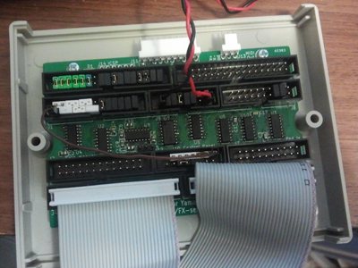
Inspired by two forum posts and with the permission of the pastor – I am, after all, the only one who ever sits down at that organ – I set forth to turn the organ into a virtual organ console by adding a MIDI out port. I opened up the organ, taking photo after photo of the various circuit boards and tracing the signals. I acquired the service manual through Yamaha (they still sell it on CD for $15 if you call). I downloaded GrandOrgue and the free Bureå Church sample set, and I began designing this board.
Page contents
Downloads
PIC peripherals used
Input algorithm
MIDI message generation
Bill of materials
More information
Technical information about FX and FS series Electone models
What's new
- Firmware Beta 0.2, with FX-20 control panel support
- Bill of Materials corrected, completed
Demonstration
Project information
Design features:
- Plug-in module using existing connectors - no permanent modifications to the organ are required
- Powered by the organ’s internal +5V bus
- Fuse and CMOS input buffers prevent short circuits created by bad firmware from damaging the organ
- Console input:
- Three manuals and pedal with unlimited polyphony on each
- Channel aftertouch on each of the three manuals
- Expression pedal
- Foot switch and knee switch
- Control panel LED status, button press and slider position, including drawbars on the preset board
- Hardware is capable of sensing key velocity on the three manuals; not yet implemented in firmware
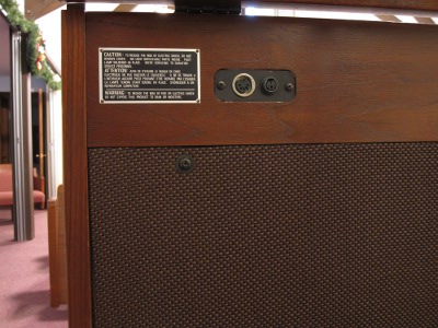
- MIDI Out port
- RS-232 port for debugging and firmware update
- Failsafe bootloader - if a bad firmware disables the serial port, the firmware upgrade can still be invoked during start-up
Limitations
The board was designed only to eavesdrop on signals; it cannot introduce signals into the organ. Therefore, the MIDI implementation is strictly output only.
Additionally, the mapping of inputs to MIDI messages is hardcoded. If you want to change them, you must rebuild the firmware.
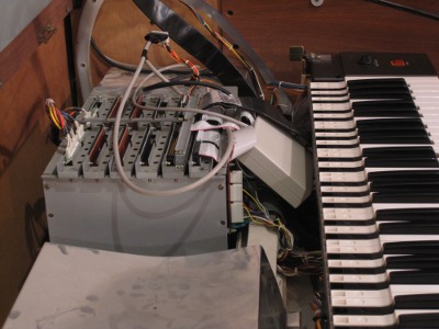
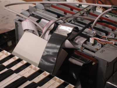
Project status
Installed, working on the FX-20-specific firmware. Basic MIDI keybord function is operational (and fun to play).
Next steps:
- Drawbars
- MIDI message configuration over RS-232, store in flash memory
- Support for other organ models with automatic detection
- Velocity sensitivity
Supported Electone models
| FS-20 FS-100 | FS-30 FS-200 | FS-30A FS-30M | FS-50 FS-300 | FS-70 FS-500 | FX-10 | FX-20 | FX-1 | FX-3 | |
|---|---|---|---|---|---|---|---|---|---|
| Keys | Planned | Planned | Planned | Yes (untested) | Yes (untested) | Yes (untested) | Yes | No (due to dual key scan drivers) Possible with PCB redesign and higher pin count PIC. | Unknown |
| Expression, Aftertouch | Yes (untested) | Yes (untested) | Yes (untested) | Yes (untested) | Yes (untested) | Yes (untested) | Yes | ||
| Control panel | Planned | Planned | Planned | Planned | Planned | Planned | Yes | ||
| Preset drawbars | N/A | Planned | Planned | Planned | Planned | Planned | Planned |
DO NOT ATTEMPT TO USE THIS MODULE ON AN FX-1!
The FX-1 has two independent key scan drivers. This module would tie the two drivers together and cause a short circuit, damaging the organ.
Downloads
IMPORTANT: These files are provided as-is. They have only been tested on the one FX-20 that I have access to. If you do not understand what you are doing, you may damage your Electone.
License
I am making the source code and design files available at no charge for private, non-commercial use, as-is. I have done everything I can to prevent this module from damaging the Electone it is installed in, but I have incomplete information about models other than the FX-20. You are responsible for verifying that this module will not damage your Electone.
If you manage to make this module work on any of the untested Electone models (see above), I'd be happy to work with you to incorporate your changes into the source here. Please contact me at: fxmidi@tsstech.org
Source code
- Bootloader (MPLAB project)
- Firmware update utility Win32 binary and source (Visual Studio project)
- Main firmware, beta 0.2 (MPLAB and Visual Studio projects provided)
Version history:
Beta 0.2:
- Adds support for control panel buttons, sliders and levers (no drawbars yet)
- Supports persistent and momentary button types
- Serial debug console changed to show control panel bitmask and masked SDi and SDO data streams
- Fixed aftertouch MIDI channels to match keyboards
Beta 0.1:
- Supports Electone model FX-20
- 3 manuals + pedal, Note on/off (no velocity)
- Aftertouch on 3 manuals, expression pedal
- Serial debug console: Shows control panel SDi and SDO data streams
Requirements for building source code:
- PICkit 3 or similar programmer, supporting in-circuit programming for the PIC24EP64GP202 microcontroller
- A sufficiently recent version of the MPLAB C30 compiler and the MPLAB IDE (I used MPLAB C30 v3.31, MPLAB IDE v8.86)
Note: This firmware cannot be compiled with XC16 v1.11 due to an internal compiler error. - Microsoft Visual Studio 2008 Standard Edition or higher (for firmware update utility)
Design files
PIC Peripherals used
A number of the eavesdropping and communications functions can be implemented using the hardware peripherals on the PIC, in order to keep the CPU load minimal.
UART1: MIDI Out
The MIDI protocol is essentially the same as RS-232, but current-based instead of voltage-based.
I have arranged the components as per the reference diagram available at midi.org,
using a MOSFET as the output buffer.
The port settings for MIDI are 31250 baud, 8 data bits, 1 stop bit, where flowing current (only a few mA) is a logic 0, and absence of current is a logic 1 (idle).
The firmware is written to use a 256-byte circular buffer. MIDI data is produced by low-priority code and consumed during the U1TX interrupt handler, which is configured to fire after every transmitted byte. If the buffer fills, the lower-priority code blocks until more space becomes available.
UART2: RS-232 communication
The debugging/firmware update port uses RS-232 at 115200 baud, 8 data bits, 1 stop bit. As with MIDI, there is a
256-byte circular transmit buffer, and the transmit interrupt is configured the same way.
There is no receive buffer; the receive interrupt handles only single-character commands.
SPI1 with DMA: Keyboard scan shift register
A 32-bit shift register holds the data read from the return lines on the key scanning cables, and also four bits identifying which of a subset of nine send lines was active, if any. The SPI1 module in master mode with DMA is perfect for reading this shift register, firing an interrupt when all 32 bits have been transferred to the PIC.
SPI2: Control panel and drawbar data
The Electone's control panel is essentially a set of shift registers, hundreds of bits long. There are three phases:
-
Read data from the control panel: Uses SYW as the clock, SDi as the data, and C1 as the active-high slave select.
To set up the first byte, C1 pulses high while C0 remains low. Data is sent in a string of 8-bit groups, with C0 dipping low between bytes. After the last data byte, one extra byte is transferred. -
Write data to the control panel: Uses SYW as the clock, SDO as the data, and C0 as the active-high slave select.
Data is sent in a string of 8-bit groups, with C0 dipping low between bytes. There is no set-up before the C0 line rises to write the first byte. After the last byte is written, both C1 and C0 are pulsed high to latch the data to the outputs. -
Read data from the drawbars: Multiple single-byte transfers, using SYW as the clock and TDi as the data.
TAC1 is driven low, then TB and TAC1 are pulsed high simultaneously to set up the first transfer. TB falls before TAC1. Immediately after TAC1 falls, the first byte is sent. TAC1 then pulses high to set up the next byte. All of the drawbar data bytes are read in this manner, plus one extra byte which reads as 0x77. TAC1 returns to its high idle state sometime during phase three, below.
Change Notification: Manual slave select and framing for SPI2
DMA unfortunately cannot be used in this hardware revision, because the C0 line is active-high and therefore cannot be used as the slave select signal without being inverted, and because the TAC1 line is not on a remappable pin. Change notification interrupts therefore inform the firmware when to activate the SPI2 module for reading the control panel and drawbars.
External Interrupt 1: Keyboard scan synchronization
The keyboard scan is synchronized to three pitch send lines: Low C, F and A#. Nine of the other ten pitch send lines are read into four bits in the shift register
via a priority encoder, so it is always possible to tell which send line is being driven.
I chose low C, F and A# because I had three pins open, and of all three-line combinations, these yield the best distribution compromise between the higher-model organs
(FS-50 and above) and the FS-20/30, which have a different driving order.
The firmware rotates the INT1 peripheral between the three lines, following the scan order and resynchronizing on the rising edge of the next expected line.
External Interrupt 2: Control panel synchronization
The INT2 peripheral watches the C1 line to determine when to activate the SPI2 module for reading the control panel outputs or inputs, and when to deactivate it.
Timer 1: 4Hz debug output timer
The serial debug output is sent about 4 times per second, triggered by Timer 1.
Timer 5: ~156kHz keyboard scan clock
For data points between the three lines, a 156kHz scan clock works well enough to drive the keyboard scanning without losing sync, no matter how the pitch knob is tuned. A ±1% adustment in the pitch becomes a ±1% timing error per timer period. 20 consecutive periods produce a ±20% error, within tolerance if the first read is done in the middle of the period.
Input algorithm
All input is accomplished with interrupt service routines (ISRs) for the various peripherals.
Reading the keyboard without velocity sensing
Current key states for all 184 keys are held as a 13-word bitmask, one word per pitch driver. The values in this buffer are constantly updated to reflect real-time key state, and the
MIDI output loop uses this buffer as input.
Contact bounce was a problem in early builds; it is now eliminated by using the two contacts on each key as a sort of hysteresis – breaking a contact does nothing;
making the key-down contact turns the note on, and making he key-up contact turns the note off.
When Timer1 reaches its period, its ISR saves the current value of PORTB, loads and reads 32 bits from the shift register using DMA.
The DMA0 ISR then extracts three values from the resulting data:
- Pitch: The number of the pitch line the organ is driving low is extracted from three bits of the saved PORTB value and four bits from the shift register. If the seven bits are not in one of the 13 expected combinations, the data is deemed invalid and not processed any further.
- Key-up contacts: 13 consecutive bits from the shift register indicate which keys (except the pedals) matching the driven pitch are at rest.
- Key-down contacts: 15 consecutive bits from the shift register indicate which keys matching the driven pitch are fully depressed.
MIDI message generation
MIDI messages are generated in the main loop, outside of any ISRs. The loop uses the various real-time state buffers as input, and keeps a second copy of each buffer that holds
the state as described by any past MIDI messages (the "MIDI state buffer").
Each iteration of the loop compares the two buffers. If any difference is found, it generates and sends
the appropriate MIDI message to reconcile the state.
This asynchronous method decouples the inputs from the output, allowing the MIDI loop to take as much time as it needs to generate the messages and guaranteeing no stuck keys as long as the MIDI connection is reliable.
Note on/off
The two 13-word key state buffers are compared with an XOR operation. Each resulting '1' bit indicates a changed key; the direction of the change (on or off) is detected from the value stored in the MIDI key state buffer. The MIDI channel and pitch are translated using array lookups.
Expression and channel aftertouch
The analog-to-digital converter (ADC) runs continuously, updating the values in ADC1BUF0..ADC1BUF3 without interrupting the CPU.
A sliding window, tracked by a 4-word buffer (one word per analog channel) provides hysteresis for the analog inputs. When the input value falls outside the window, the corresponding
MIDI message is sent and the window updated. Repetitious messages with the same MIDI data value are filtered out.
I have found that I also need a rate-limiting mechanism of some sort.
Hypothetical requirements for full MIDI operation
Full MIDI operation would be more difficult, because the module would have to react instantly to the changing scanning signals from the organ's system controller. It requires more components and more board area, increasing the cost of the module.
Note on/off
The return lines on the organ are pulled up with 4.7kΩ resistors to +5V. The module would need only to drive them low at the appropriate time.
Hypothetical requirements:
- 28 parallel open collector outputs
- Outputs must be directly tied to pins on the PIC, because a shift register would have too much delay. Therefore, the PIC must have 44 or more pins.
- For safety, outputs should be buffered in a way that allows the pin to function as an input when not driven low, yet prevents the pin from sourcing current (diode and pull-down resistor at each pin).
Analog controllers
The analog signals from the organ cannot be directly overridden, therefore the PIC must function as an analog repeater when not being controlled by MIDI.
Hypothetical requirements:
- 4 analog input channels
- 4 independent hardware PWM output channels with external low pass filters
Control panel
Like the analog inputs, the control panel cannot be directly overridden and the PIC must function as a man-in-the-middle.
The control panel could potentially operate in one of three useful modes, or a combination thereof: Passthrough (eavesdropping), instrument control (masquerade input), or control panel override (block input, masquerade output).
Hypothetical requirements:
- Two SPI modules in slave mode with DMA operating together for input
- Two SPI modules in slave mode with DMA operating together for output (open collector, prevent sourcing current)
- Double-buffered; one full cycle delay in each direction if passthrough
Bill of materials
| C1..C4, C15, C17: | Filter capacitors: | 0.1µF, ≥5V | (0805) | 6× Any appropriate |
| C5..C6: | Charge pump capacitors: | 1µF | (0805) | 9× Any appropriate |
| C8..C10: | Stabilizing capacitors: | |||
| C11..C14: | DC-blocking capacitors: | |||
| C7: | Regulator output capacitor: | 10µF | (0805) | Any appropriate |
| C16: | Stabilizing capacitor for PIC: | 10µF tantalum | (3216 metric) | Any appropriate |
| D1: | Status LED: | Any color | (1206) | Any appropriate |
| F1: | Fuse: | Fast response, 125mA | (1206) | Littelfuse 0466.125NR |
| J1, J2: | Headers for Solo manual | 26-pin IDC | 2×13, 0.1" pitch | 2× On Shore 302-S261 |
| J3..J6: | Headers for Upper and Lower manuals | 34-pin IDC | 2×17, 0.1" pitch | 4× On Shore 302-S341 |
| J7,J8: | Headers for pedals | 20-pin IDC | 2×10, 0.1" pitch | 2× On Shore 302-S201 |
| J9, J10: | Headers for control panel with power supply | 16-pin IDC | 2×8, 0.1" pitch | 2× On Shore 302-S161 |
| J11: | Header for analog inputs | 10-pin SIP, right angle | 0.1" pitch | TE Connectivity 1-640455-0 |
| J12: | RS-232 header | 3-pin SIP, breakaway | 0.1" pitch | Any appropriate |
| J13: | MIDI header | 3-pin SIP, right angle | 0.1" pitch | TE Connectivity 640457-3 |
| J14: | Programming header: | (Not placed - program the microcontroller by holding a free-hanging male header in these holes) | ||
| Q1: | MCLR input isolation: | N-channel MOSFET | (SOT-23) | 2× ON Semiconductor 2N7002ET1G |
| Q2: | MIDI Out buffer: | |||
| R1, R2: | MIDI current-limiting resistors: | 220Ω | (0805) | 2× Any appropriate |
| R3: | MCLR pull-up resistor: | 10kΩ | (0805) | Any appropriate |
| R4..R7: | Analog input current-limiting resistors: | 100kΩ | (0805) | 4× Any appropriate |
| R8: | Current-limiting resistor for LED: | 4.7kΩ to 10kΩ | (0805) | Any appropriate |
| R9..R18: | Keyboard pull-down resistors:
FX-20: None FX-10: R13..R18 required FS-70/500: R9..R12 required All others: R9..R18 required | 1MΩ | (0805) | 10× Any appropriate |
| U1: | Microcontroller: | PIC, 60-70 MIPS | (SOIC-28) | Microchip PIC24EP64GP202 |
| U2..U5 - | Shift registers: | CMOS, 8-bit positive logic, 10MHz operation | (SOIC-16) | 4× 74HC165 |
| U6: | 6-bit buffer/inverter: | CMOS | (SOIC-16) | CD4049 |
| U7: | 6-bit buffer/converter: | CMOS | (SOP-16) | CD4050 |
| U8: | Serial line driver: | MAX232 | (SOIC-16) | MAX232 |
| U9: | Voltage regulator | 5V in, 3.3V out, LDO | (SOT-23A) | Microchip MCP1702T-3302E/TT |
| U10: | Priority encoder: | CMOS, 9-input active low | (SOIC-16) | 74HC147 |
| N/A - | Enclosure: | 5"×3"×1.5", open on long sides | Hammond Manufacturing RM2015S | |
| N/A - | PCB: | Special order | 11 in2 | From BatchPCB |
| N/A - | Back panel plate: | Special order | From local machine shop - Dimensional drawing here | |
| For ribbon cables: | ||||
|---|---|---|---|---|
| N/A - | Bulk ribbon cable | 34- or 40-pin | 0.05" pitch | Spare IDE/Floppy cable or 2x Assmann H1CXS-3436G (incl. one 34-pin connector per cable) |
| N/A - | IDC connectors | 34-pin | Snap-on | 4× Assmann AWP34-7540-T-R |
| 26-pin | Snap-on | 2× On Shore 101-266 | ||
| 20-pin | Snap-on | 2× On Shore 101-206 | ||
| 16-pin | Snap-on | 2× On Shore 101-166 | ||
| For analog cable: | ||||
| N/A - | Cable: | 9-conductor plus ground, 3’ length | Shielded | (bulk cable, 24AWG stranded) |
| N/A - | Connectors to boards: | 10-pin, keyed | 0.1" pitch | 2× Molex 0022013107 |
| N/A - | Terminals for connectors: | 20× Molex 0008500113 | ||
| N/A - | Connector to existing cable: | 10-pin | 0.1" pitch | TE Connectivity 4-644457-0 |
| For MIDI jack: | ||||
| N/A - | Cable: | 2-conductor plus ground, 3’ length | Shielded | (surplus microphone cable) |
| N/A - | Connector to board: | 3-pin female, keyed | 0.1" pitch | TE Connectivity 1375820-3 |
| N/A - | Terminals for connector: | TE Connectivity 1375819-1 | ||
| N/A - | Rear panel connector: | Panel mount | (DIN-5 180°) | CUI SD-50LS |
| For RS-232 jack/dongle: | ||||
| N/A - | Cable: | 2-conductor plus ground, 5’ length | (bulk cable, 24AWG stranded) | |
| N/A - | Connector to board: | 3-pin C-Grid III female, keyed | 0.1" pitch | Molex 90156-0143 |
| N/A - | Terminals for connector: | C-Grid III | 3× Molex 0901192120 | |
| N/A - | Rear panel connector: | Panel mount | (Mini DIN-3) | CUI MD-30CV |
| N/A - | Plug for rear panel connector: | Free hanging | (Mini DIN-3) | CUI MD-30 |
| N/A - | Serial connector: | 9-pin female D-sub | (DE9/DB9) | Norcomp 171-009-203L001 |
| N/A - | Backshell hood: | Plastic backshell hood | (DE9/DB9) | Norcomp 977-009-010R031 |